Engineering & Development
System Requirements
To design a reliable custom battery pack, the first step is to define the electrical and mechanical system requirements. Voltage, capacity, discharge rate, and physical constraints determine the cell configuration and final pack architecture. Select the most suitable cell chemistry, model and ensure optimal electrical performance, mechanical reliability, and long-term quality.
1. Voltage Requirements
The operating voltage range of the device dictates the number of series-connected cells required.
Formula: Pack Voltage = Cell Nominal Voltage x Series (S), Maximum Voltage = Cell Max Voltage x S
2. Capacity & Discharge Requirements
Capacity and discharge rate determine the number of parallel cells.
Formula: Pack Capacity = Cell Capacity x Parallel (P), Continuous Discharge = Cell Max Discharge x P
3. Series / Parallel Combinations
Applications requiring both higher voltage and higher energy use mixed configurations (e.g., 3S2P, 4S3P).
4. Dimensional Constraints
Cell type and mechanical layout determine the final pack shape and thickness. Cylindrical cells: high cycle life, robust. Pouch/Polymer cells: thin, flexible shape. Prismatic: high volumetric efficiency.
Electrical Design
Lithium batteries require dedicated protection and management circuits to maintain safe and optimal operation. This includes voltage, current, and thermal protection, as well as optional system communication and monitoring. We work with your team from concept to production to ensure the lowest failure rate and long-term stability.
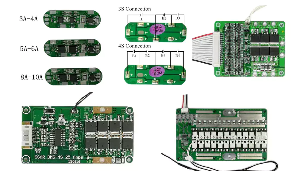
Protection Circuit Module (PCM)
Suitable for compact consumer-grade and low-to-mid power applications. Essential safety protections include:
Overcharge / Over-discharge, overcurrent, short circuit, over-temperature.
Battery Management System (BMS)
Used for more complex or higher-power packs. Typical functions include:
All PCM functions, fuel gauge / SOC estimation, cell balancing, thermal monitoring, data logging, communication interfaces: SMBus / I²C / UART / CAN, status indication
Custom Electrical Design
We design and validate the full electrical architecture of your pack:
Cell selection & qualification, PCM/BMS selection or custom development, protection logic tuning, thermal management strategy, verification testing (voltage, current, impedance, cycle life, safety)
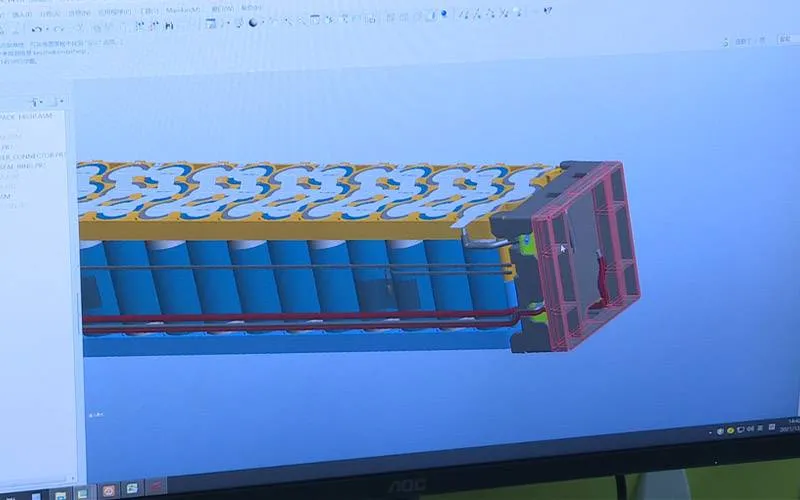
Mechanical Design
The mechanical structure of a battery pack must support electrical performance while protecting internal components from mechanical, thermal, and environmental stress. Using advanced 2D/3D tools and automated prototyping equipment, we design enclosures with high precision and stable long-term structural reliability.
Key mechanical design elements:
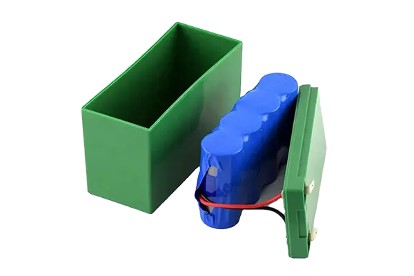
Enclosure / Housing (shrink-wrap, injection-molded case, metal chassis)
Insulation & Isolation layers
Cell holders and impact protection
Wire routing & terminals
Connector selection (Molex, JST, custom)
EMI / ESD considerations
Primary Mechanical Safety Functions:
Over-voltage / under-voltage protection placement
Short-circuit isolation
Thermal dissipation pathways
Vibration & shock resistance
Structural integrity under compression
Battery Pack Integration
A battery pack integrates multiple elements into a safe, stable, and production-ready power system. Components typically include:
Individual cells (matched and graded)
PCM/BMS
Interconnects & harness
Enclosure / insulation
Sensors (NTC, thermal fuse, etc.)
Cell Interconnection
Depending on application requirements, packs may use:
Spot-welded nickel strips
Busbars
Soldered tabs (for polymer cells)
Laser welding for high-precision connections
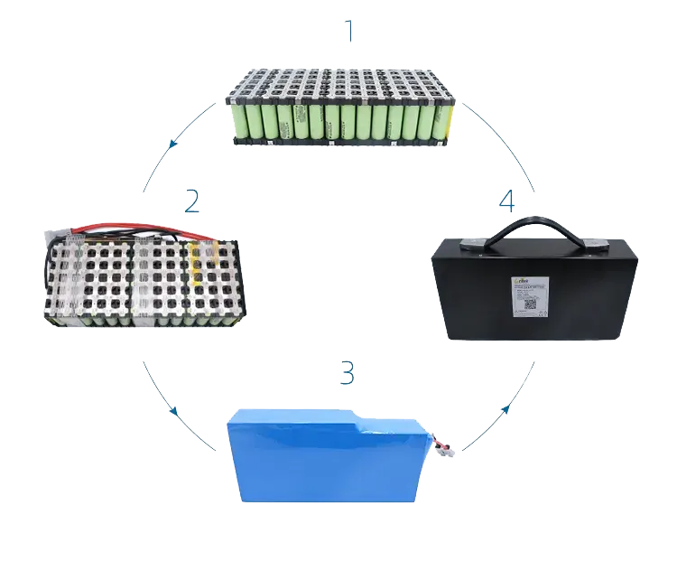
Integration Workflow
Cell grading & matching
Series/parallel assembly
Interconnect welding
PCM/BMS installation
Wiring & harness
Insulation and mechanical reinforcement
Enclosure installation
Functional & safety testing
Our electrical, mechanical, and industrial engineers collaborate throughout the entire project lifecycle to ensure stable performance, manufacturing consistency, and a minimal failure rate.
Charging System Design
Lithium batteries must be charged using the CC/CV (Constant Current / Constant Voltage) method:
Charging Profile
Constant Current (CC): Battery charges at a fixed current until it reaches the charging voltage limit.
Constant Voltage(CV): Voltage is held constant; current tapers down.
Termination: Charging stops when current falls below a set threshold.
Critical Charging Considerations
Charging voltage (per chemistry)
Maximum charging current typically(0.5C to 1C)
Charging temperature window (0°C-45°C typical)
Fast-charging requirements
Power supply capability
Linear vs. switch-mode charger selection
Linear: low cost, compact, ideal <1A
Switch-mode: high efficiency, fast charging, low heat
Modern charge ICs integrate safety features including thermal monitoring, timer cutoff, and input power protection.
We understand each application has unique power requirements. With the industry leading technical knowledge and extensive experience, we can customize cells, management circuits, housings, battery packs, chargers and system integrations to meet your specific application needs. If you did not find our standard products that can meet all your requirements, simply contact us. Our well experienced team will work closely with you to understand your requirements, develop a custom solution, and deliver a high-performance battery tailored to your particular needs.